With all these modules and sub-systems in the design, its sometimes hard to picture what's where. Lets take a recap on what the modules are and what its like in the chicken coop:
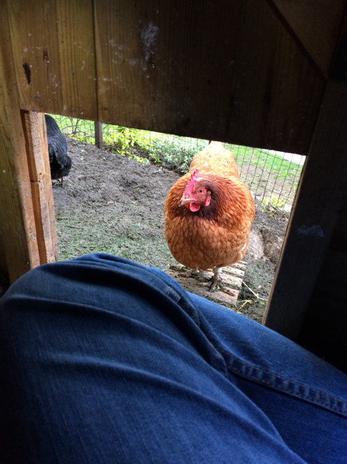
Firstly, its important to recognise that any work in the coop will involve supervision. Today we are being supervised by Clucky, at other times we may be watched by Lotty (aka Mother Hen). At the end of any works, it will be necessary for an inspection and final tidy up to be performed. Sometimes you will even be told to leave, for example if you are trying to work late. This is explained by the girls coming home to roost - irrespective of the state of the coop, any tools, open boxes, diagnostic kit, etc. Its hard to work when all you can see is a line of fluffed up chickens with either their beak, or worse still their bottoms, in the way of what you are trying to work on.
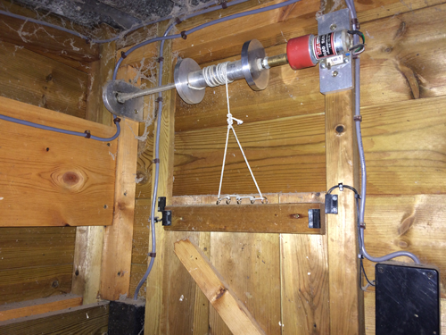
Starting on the left, we have the Solar Panel conditioner module.
Before anyone asks, that's not a mains cable in the picture - we are off-grid, its just a handy piece of thick 3 core cable that carries the Rotator drive signals.
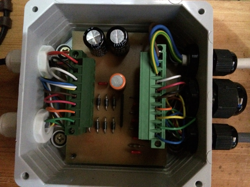
The conditioner panel connects to the Solar Panel Positioner module, yes it is mounted straight on the bar, but space is limited to take pictures from.
Next to the positioner is the main pop hole door, this has the door motor assembly and the door sensors, which are reed switches. The two black boxes are junction boxes and will eventually provide connectivity for upgrades that deliver an infra-red beam across the pop hole door and RFID sensing.
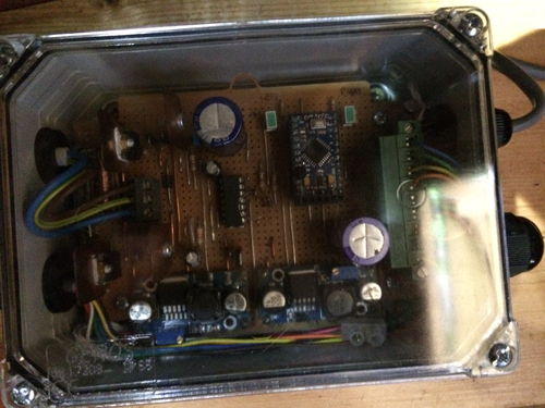
Moving right we get to the main control panel.
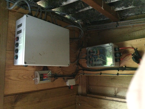
Below the main panel is the master on/off switch. When its off, the auxiliary power socket can be used to charge up the batteries.
On the right panel is the Voltage and Current sense module that measures the battery state and solar panel state.
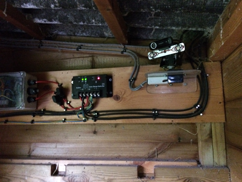
Next to the sense module are the two protection fuses for over current on the battery or the solar panel.
Next to this is the Solar Charge Controller, which is shown when the module was faulty, hence why the output load pins are not used.
Finally, on the right is the webcam module that provides pan and tilt via two servos and a pair of PWM driven 1 watt LEDs so that we can adjust the light levels in the coop.
The two notches in the bottom of the picture are where the roosting bars go across the coop. These are often removed to increase the human space when maintaining the unit.