
Now that I have a design for the feeder enclosures, we are half way there, but right now, they are just on my screen. How can I convert these to the parts I need. They need to be water and weather proof and I only need one of each, so commercial manufacturing is out of the question.
I have a 3D printer, an Ender 3-V2, so that is the obvious thing to use. However, PLA is not a great choice for parts that will be left outside, since they will absorb moisture, but on the flip side, its cheap and hence ideal for prototyping and importantly, I've got plenty of material to work from and I can use up some of the partial spools during the prototyping process.
The designs are sent to the printer and prototypes start to come out and problems start to be identified and resolved. Mostly these are around tolerances. 3D printing is an additive engineering approach, where material is added to the final product, compared to a lathe or CNC machine, which is subtractive engineering, since bits are cut off to reveal the previously hidden part that was trapped inside the original material.
A side effect of 3D printing is that when printing threads, if you print two mating halves of the same thread, they will not fit together, even though the exact same dimensions work perfectly if you were to use a lathe or CNC machine. The reason is that the 3D printed filament is pushed out of a nozzle and extruded onto the existing part, meaning is spreads out horizontally a little and this results in the tolerance issue. The solution to this is to ease the threads a little, either with a little sanding on the peaks, or by adjusting the thread size to be a little larger. between 2% and 3% seems to be the right sort of ball-park number to adjust by, according to research done others facing the same issue and I concur that the numbers seem to be right.
Sometimes, you will find the required thread in Confusion 360, in other times, you need to add in a new .xml file that contains the relevant thread characteristics, so that it can be modelled, then sliced and ultimately printed. A really useful feature of Confusion 360 is at the next software update, it will bin your custom threads and you won't realise until the next print when things don't work. If only there was a way to persist customisations.
It quickly became apparent after waiting days for a single print to be produced and working my way through multiple spools of material, that there is no point in trying to print the whole assembly each time, just focus on one feature, get the sizing right on that, then move onto the next one. This is much quicker and uses a lot less material. Even after taking measurements of the neck of the water feeder and the neck of the food feeder using thread pitch gauges and various measuring instruments, it took several goes to get things to fit, then to get them to fit with enough tolerance that they should cope with the expansion and contraction through the year. I just hope that the tolerances map to other materials and I must make a mental note to check that my custom threads are still present when I do the next prints.
Water feeder
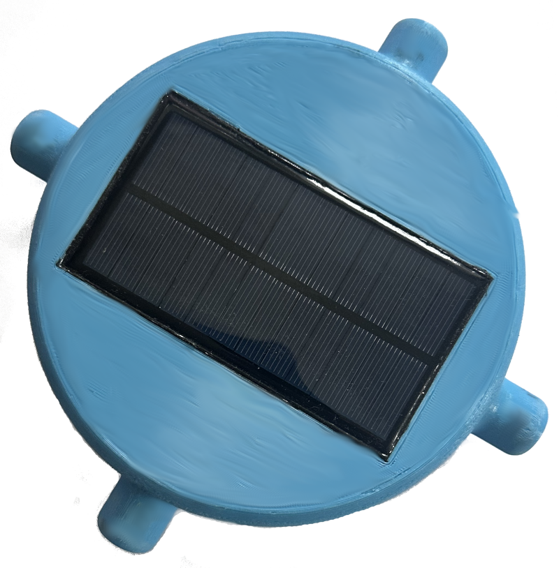
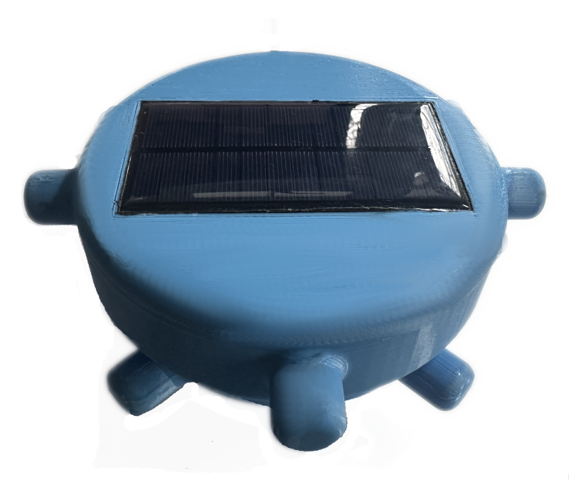
The resulting water feeder assemblies look like this, you may note that they are supporting the correct colour scheme to match the Gaun feeders.
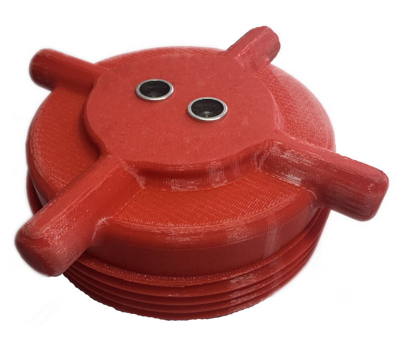
This is the top view, showing the solar panel installed and sealed into the unit. The 4 small handles that that stick out are present to allow easy removal of the top, this is the same arrangement on all components, quick assembly and disassembly
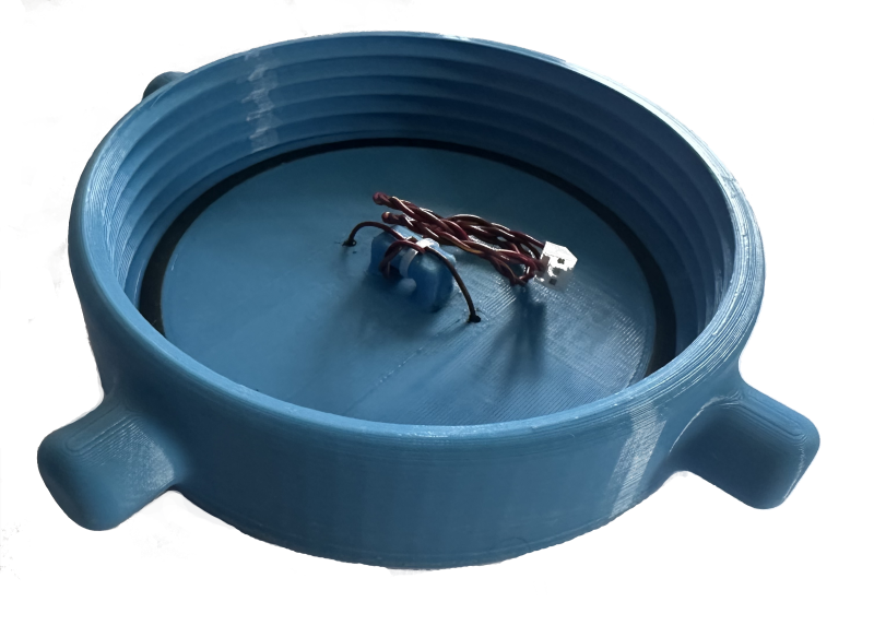
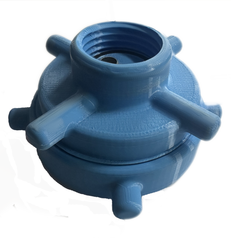
Inside the top, you can see the solar panel wires on their mechanical support, along with the black square O-ring and the coarse thread that mates with the opposite half of the unit.
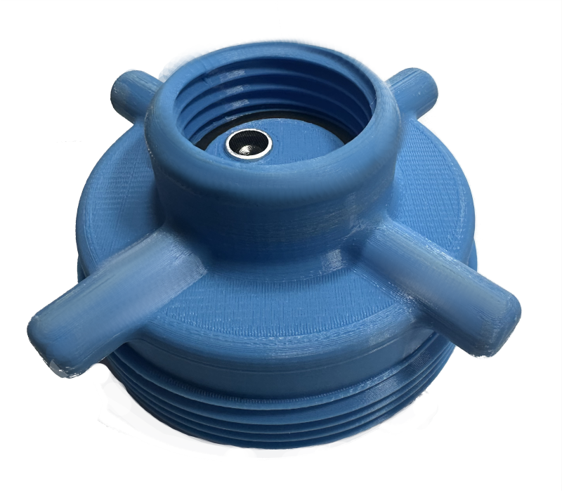
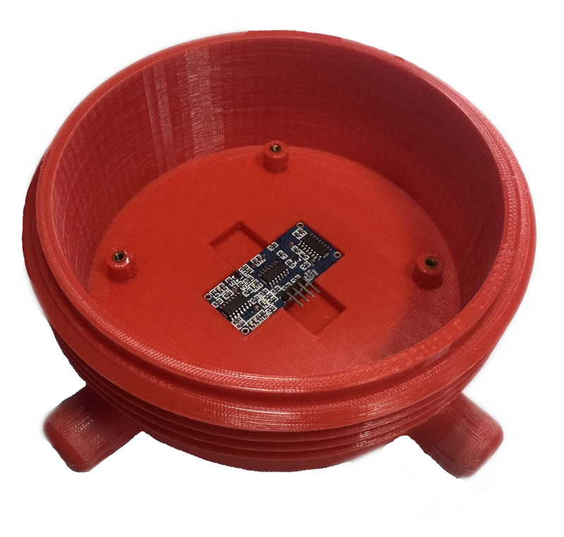
The next item is the bottom component. The thread is what connects to the top of the water feeder. Half of the ultrasonic sensor can also be seen, along with the square O ring in the bottom to seal things.
The ultrasonic module can be seen in its recessed pocket. 4 mounting posts are present for the PCB to mount onto. Brass inserts have been driven into the plastic using a little heat. This means that the threads will survive better than if they were just into the plastic. I have had reasonable success with tapping into 3D printed plastic holes, when I'm not expecting to need to pull an item apart frequently, but they don't last if you do end up disassembling things a lot. 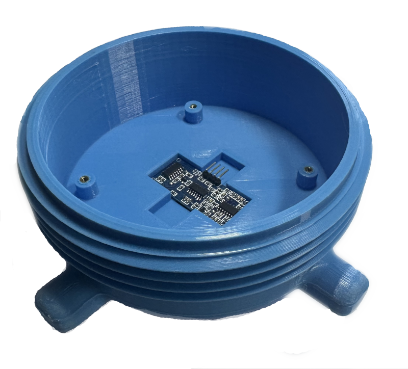
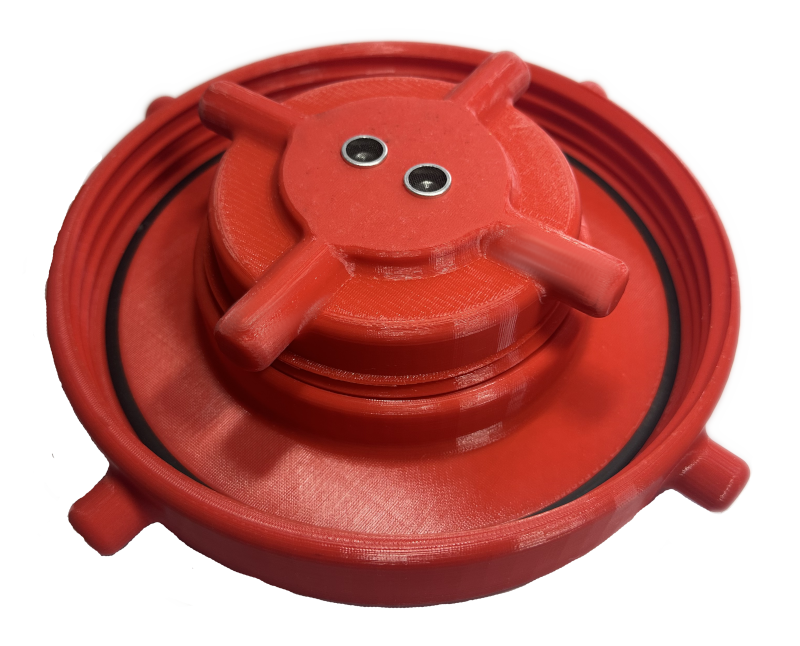
The assembled unit looks like this from the top
The bottom view of the whole unit. This can be left laying down when refilling the unit. The solar panel is flush with the top so its partly protected.
Food feeder
The Ender 3-V2 3D printer has a print area of 220mm x 220mm x 250mm high. This is perfect for most things I need and indeed, if I rotate the water feeder assemblies by 45 degrees, then the grab handles that are used to assemble and disassemble the parts will go into the corners of the print bed and the part can be successfully printed, but its getting a bit tight on space.
The problem is when I look at the food feeder, it has a diameter of 250mm for the lid and 290mm when the grab handles are added on. This means that my Ender 3-V2 is not going to do the job. Luckily I have like minded friends and one of them has an Ender 3 S1 Plus, which has a 300mm x 300mm x 300mm high bed, so my 290mm part will just fit onto that. The printer is borrowed, some ales exchange hands in the local tavern and the food feeder parts start to materialise.
The same challenges occur on threads on these parts, just using more material to build the prototype parts. Matching to the larger, much coarser threads took a bit more time, but I prevailed and I end up with the following parts, which then get the solar panels sealed in with some black silicon that I had left over from a previous project.
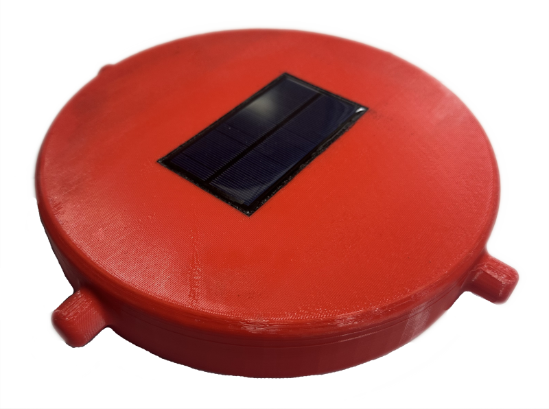
Top of the food feeder, the part that connects to the main body of the feeder. Note that the solar panel is the same size as the water feeder, which gives a sense of the difference in scale.
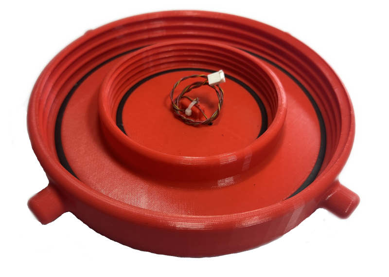
The inside of the top shows the two threads, the outer one goes onto the feeder body. The inside one accepts the bottom half. Note that the design is identical to the water feeder, in terms of the solar panel wiring and the square O rings. Technically the outer one is not required, but it was simple to add during design, hence its present.
Next is the bottom view of the bottom component. The ultrasonic sensors can be seen. One element is the transmitter, the other is the receiver. The similar design to the bottom of the water feeder can be seen too. The only difference is the lack of the neck and thread, which is not required on this module. This unit screws into the smaller of the two threads on the unit above.
Inside view of the bottom part, showing the same internal structure as the water feeder.
The completed food feeder assembly, shown upside down below. The top view is not shown, since its identical to the top view shown above, since everything is concealed below it.
These parts are only printed in PLA at the moment and have had some initial surface sanding in places to remove a couple of rough edges, hence the blemishes in some of the pictures. They will be re-printed in PETG or some other suitable external grade plastic at a later date, once the designs are fully working. This is because PLA is hydroscopic, so it will absorb moisture and eventually crack when that water freezes in the part. It is possible to add a layer of lacquer to the parts to provide better protection, so this might be done in the meantime. PETG will be a better option, since its more robust and doesn't suffer from the moisture problem that PLA does.
It is worth noting that 3D printed parts are not normally solid material, they have deliberate voids within them, the level of filament to air is known as the infill density. Values of 20% are common since this makes things strong enough and importantly, a lot cheaper, and lighter since less filament is used. Printing time is also reduced as less filament is used.
A benefit in this project is that those air pockets generate a thermal gap between the outside temperature and the inside temperature, much in the same way that people line their greenhouses with bubble wrap in the winter months. It will however mean that any temperature measurements within the enclosure may be a little bit off compared to the outside temperature due to self heating from the power dissipation from the electronics being used. I need to measure this difference, once I have a the device sleeping properly.
Now I have the enclosures, I can focus on the board and its firmware.