I deliberately carried forwards the OLED display that was part of the initial version 1 platform, so that I could use the existing diagnostic display, during initial testing of the board. However, this was only a short-term need as I now know that the OLED displays do not last, they fade over time and the only solution is to replace them, something I had to do a couple of times in the old design. My last display was the one used on the temporary display board, the display is shown in this article. The 0.96 inch OLED is monochrome and has a resolution of just 128 x 64 pixels, which is not good for any modern design.
A TFT display is the obvious replacement, so the display card was modified and the 1.8 inch colour TFT, with 128x160 pixels replaced it. This allowed for more information to be presented in less menu pages, so the user interface could be simplified, the colour display allowed for the removal of reverse video highlighting, which was all the OLED could provide. Now there is colour sensitive information showing Error, Warning and OK, using the standard Red, Amber, Green traffic light approach.
The larger screen is great, but it causes a different problem. I'd like to put it on the main chassis, but the width of the display is too large for the box, even if the screen is rotated 90 degrees. After mulling over the options, I decided to have the display as an option that I can simply insert into the connector on the board when I need to use it. The next challenge is that it would get in the way if it was over the main PCB during upgrades, diagnostics and fault finding. Similarly, it can't go to the left, outside the box, when its installed, since the box is taller than the connectors.
The answers to these problems are fairly obvious, make a board with a connector on the left and right hand side that has the same pinout and allow either to be used. Make one with a left connector installed and one with a right connector. Use the left installed unit on the main coop and the right installed connector on the bench when working on the coop.
As to how to work around the height issue, that's quickly resolved with some long pin strips and a push socket, just solder them together and you end up with a modern version of a bus extender, which fits into the boards connector allowing the diagnostic display to be used.
As I wanted everything that goes into production to be a proper PCB, a simple board was designed, sent off to PCBWay using their cheap shipping option, and being a small PCB less than 100mm x 100mm, it cost next to nothing to manufacture as they are effectively using the dead space between the larger customer boards when they panelise the PCB's for manufacture. Waiting a week or two for shipping wasn't going to be a problem, since I still had the development board and had already made the extension header.
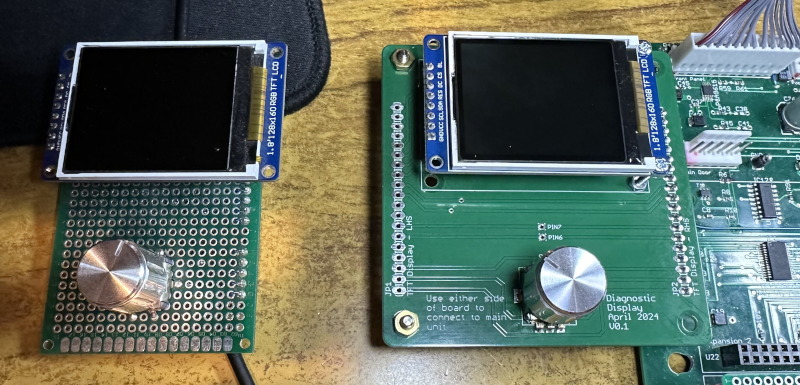
The picture below shows the development board and the desk based diagnostic display. Another unit exists with the connectors and mounting posts swapped over, this re-used the display and rotary encoder from the prototype board, so nothing really ends up being wasted. Even the protoboard went back into stock for next time.