
Two days before close of business for Christmas in 2024, a parcel arrives in the post, its the consumables PCB's. Now I have something to work on when everyone wants a break from the festivities.
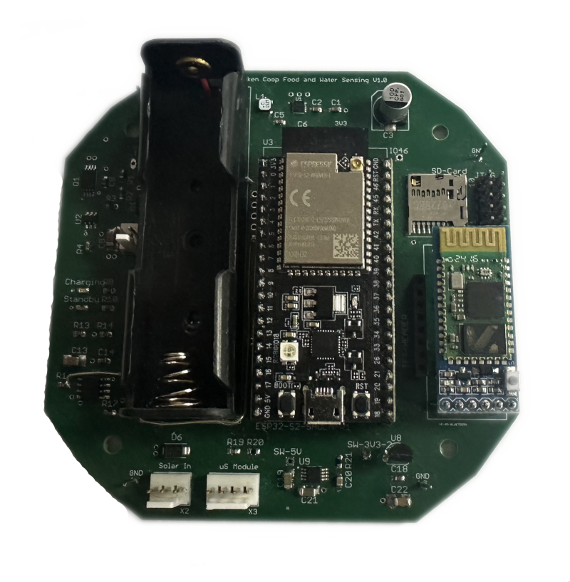
The stencil is used to help assemble the boards and two boards are populated, from the set of components that will ultimately allow 4 boards to be made, 2 for production and two for development, since I always want a spare board that I can swap into the coop if I need to when something fails. The new modular system is really coming together.
After a bit of assembly and cleaning, the boards are ready for testing, using the code base that was forked from the front panel software. It already has the Bluetooth and MQTT components in it, although I ponder if now is a good time to make the first module using the Espressif ESP-IDF, rather than the Arduino framework. This should be the simplest module of all of them, but conversely, the power management part is new. I therefore keep to the Arduino framework and will use this module for migration once everything is going.
Testing
The board gets the usual smoke test with no modules present. The battery charging module is tested to make sure it works and won't decide to set my office alight. This is followed by initial confidence testing and I find my first mistake. The Bluetooth module needs 5V, not the 3.3V that is connected to it, since it regulates down the power locally within the module. A couple of bodge wires later and that is sorted out. I had also forgotten to add the current sense capability on the charge controller, so a second wire is added for that.
I also find that the SD Card socket that I'd used, I had misread the datasheet and assumed the pins were at the back of the socket where I wanted them but in reality, it is rotated 180 degrees, so although I wanted the card to go in at the top, it actually goes in at the bottom. This just works, but its not easy to get in and out due to the TFT connector and a resistor that are in the same board area. This will need to be rotated 180 degrees in the next board respin. This is not difficult, just annoying.
Other than those two omissions, everything else works as expected and after some code changes, the module is working as expected and I can generate the required MQTT telemetry messages, status messages and react to commands such as Insomnia requests. 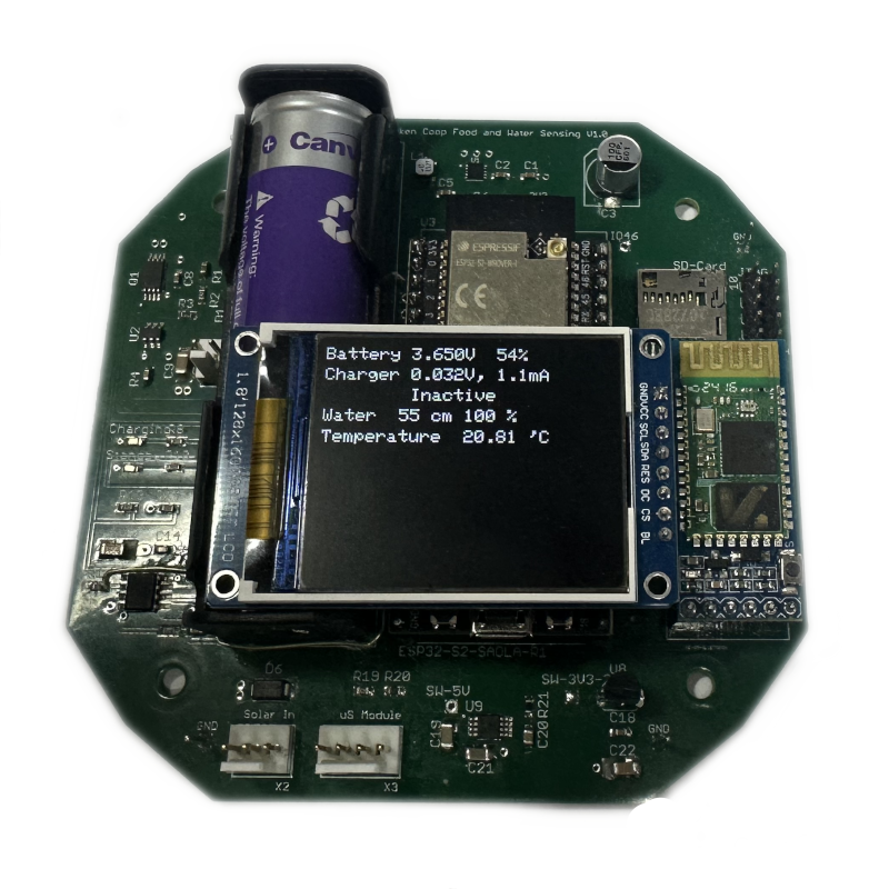
The diagnostic display is removable, since it doesn't need to be present when the modules are in operation.
A nice thing about the TFT displays is that they are a write only device that never sends any form of response back, so the code can be implemented and just left there, it doesn't care if the display is present or not. If you want it, install the display and hit the reset button.
The water sensor is showing a measurement, since the ultrasonic module (marked uS module, X3) is not connected.
The firmware knows the height of the container and its relative position compared to the top. The water sensor is at the top of the neck and interestingly, when the sensor is just in the housing, it misreads the height as it gets echoes from the thread, however once its installed properly in the water feeder, no such false echoes occur since the plastic is smooth. I knew that the sensing angle could be a problem on some ultrasonic measuring devices, it looks like I'm on the border of lucky with these ones.
Now I can turn my attention to the low power modes and how to save power and work within the power budget that is available.