After a significant amount of time and effort, its finally time to bring up Chicken Coop version 2. Its a year later than I had originally planned, but life's priorities change and last years summer was virtually non-existent which prevented the required maintenance and that is a pre-requisite for the install, so we are where we are. On the positive side though, the new Electronics and its firmware are much better with many additional features and a handful of undetected bugs and a couple of known ones too.
Its time to start the install. This is easier than the prep work, simply clean out the chickens as normal, remove the rubber mats, let the chickens out to roam in the garden and get to work, after admiring how well the coop has come up.
The process is simple, fix the plastic boxes on the wall, using the existing fixing holes where possible, since that is then one less hole for red mites to infest later in the year, it will also make it look better at the end, since less holes will be visible. As with the previous iteration, upgrades are easy once its installed and working. This time, swapping boards will be even simpler than before.
The installation process needs to try and keep clutter to a minimum in the coop, so that if I have to stop for any reason, then the coop is still safe for the hens to sleep in. In real terms, this means keeping cabling clipped in and if loops need to be left un-terminated, they can be tucked behind the wooden panels, keeping them away from the hens. Installed enclosures then just need their lids fastened on overnight, to stop their insides being pecked and to keep moisture and dirt out.
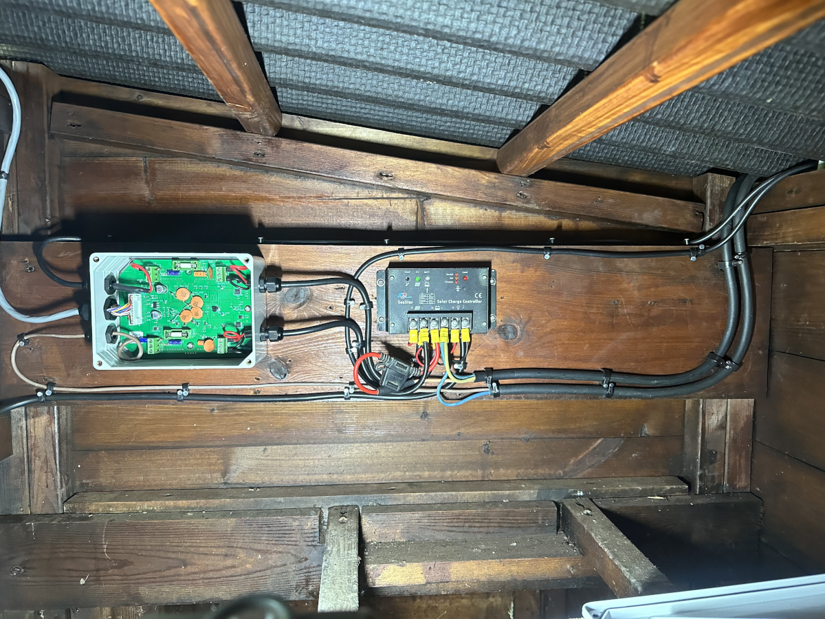
First up, is the charge controller and power sensing module, since without power, nothing will work. The cleaned up charge controller is in, the screws are replaced with stainless steel ones, so they should last longer than the previous ones. Battery power and Solar power come in from the larger rubber cables on the right, route via the power sensing module so they can be measured, then fed back to the charge controller, so it can manage the battery charge and system load, which in this case is the Chicken house controller and all its modules.
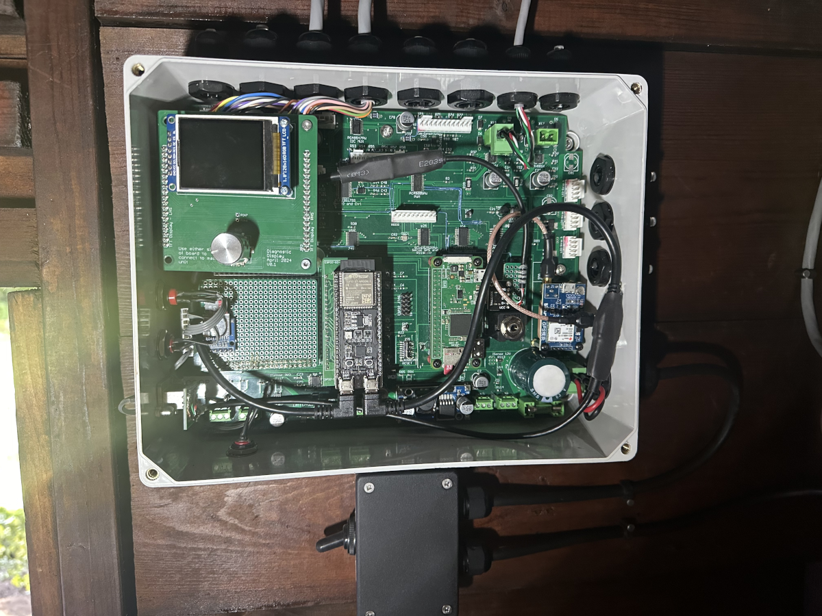
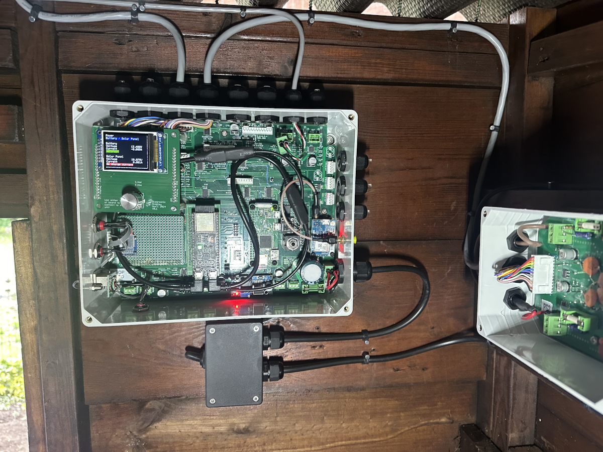
Once that is all in, then its time for the main module.
The two large black cables are USB cables that need to be replaced at some point with shorter cables and the correct 90 degree connectors. The main board can also be seen with the ESP32-S3 module on its adapter board, plus the Diagnostic Display module is in, it hangs a little to the right, since there are no mechanical fixings between it and the main board, this will need addressing at some point. Below the main unit is the master power switch, this allows the system to be easily powered off from the main door, even when its dark. This is now a sealed box, as opposed to a bare switch on a bracket in the previous iteration, so the switch should last longer.
The front panel is installed, but not shown, since the firmware for the front panel wasn't ready at the point of installation, so it wasn't doing anything useful yet.
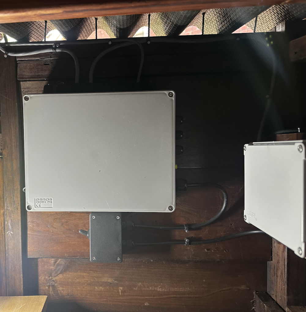
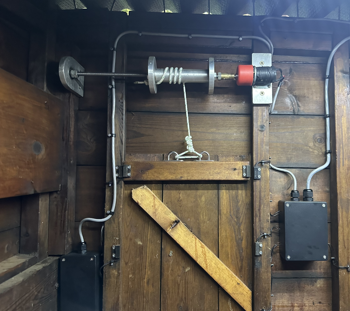
The door lifting mechanism gets installed as do the joint boxes either side of the pophole, these are just a box full of connectors and the individual sensors, using small wires, so they can't go in via a cable gland. Silicon sealant will be used to seal it all up, once its proven to all work, since silicon sealant is well known for working, until it doesn't. A small hole is added to the bottom of each box, just in case any moisture gets in, hence preventing the problem that the previous system had with water build-up. All screws are stainless steel, again to resist corrosion.
The main drive motor, shown on the right (with the red gearbox) is now encased in self amalgamating tape, in an effort to stop moisture and Diatomaceous earth power getting into the motor as neither are good for the motor. Generally they only last a couple of years.
Heat dissipation from the motor will be reduced due to the insulating properties of rubber, however, its mounted using a metal bracket to a metal block, albeit with thin material, but the main shaft goes through the metal gearbox and into the motor, so there are heat paths for dissipation. Additionally, the motor only runs for short periods a couple of times a day, so its only during an extended number of repeated movements in a short time that this may become an issue.
Testing time
Now that its all in, its time to test it. All modules had been bench tested before installation, so I know that the hardware is good. Similarly, all firmware was up to date before installation. Testing goes well and the Diagnostic display can be used to show the various sensor states.
Testing goes well, however a couple of the door sensors are not quite right, they are just a reed switch in a sealed glass tube that is held in a plastic carrier that has been filled with resin. As they were working on the old unit and are sealed units, I re-used them, but several were difficult to remove, due to very rusty screws and perhaps they became damaged somehow internally. Replacement sensors are installed and things start to work as expected. The diagnostic display really helps in this regard. No laptop, no serial consoles. There is even space to leave the diagnostic display installed when the cover goes on.
Chicken Coop v2 is now on-line :-) The covers can now go on as that's enough for the day. There is still plenty of work to do though.