
As has been mentioned on several other articles, the Inter-Integrated Chip (I2C) protocol is very popular in Electronic systems, since its a very simple bus that only needs two pins and two pull-up resistors to implement, a clock and a data pin, yet it allows two way data transfer, under the control of the bus master device, which is generally the main system controller. It is a multi-device bus, with each device having a unique address, which is defined by the device family and generally a couple of pins on the chip that allow you to address more than one of the same on the bus.
The unique address is actually two addresses, one for reading data and one for writing data, these are adjacent address, using the standard read, not write method (R/~W, or read=0 and write=1), this is in the least significant bit on the 8 bit address field, resulting in a 7 bit address, or ID's of 0-127. There are 8 bit and 10 bit addressing modes, but the devices need to support those features. In this case, there are not that many devices, so 7 bit addressing and bus multiplexing is used.
The I2C bus protocol specification can be found on NXP's web site, since it was invented by Philips in 1982 and they were renamed to NXP in 2006. A quick guide to I2C is present on Analogue Devices web site. Other Electronics companies have implemented compatible protocols and its now ubiquitous in Electronic systems.
The data transfer speed of I2C can be virtually anything, since its clock is generated by the master and everything happens relative to the clock on its different phases (the rising and the falling edges). Typical speeds are 100KHz, 400KHz and there is and even a low speed 10KHz mode. Higher speeds of 1MHz, 3.4MHz, 5MHz are also quite common now, but both the master and slave devices must support the speed to communicate correctly. Each device's datasheet will state the capabilities of the device.
There are obviously a number of competing bus protocols that are designed to solve specific problems, such as Maxim's 1 wire protocol, which does everything on only one wire, plus a system ground pin, technically making it two. Note that nothing is mentioned about the power supply, which is transferred on the data pin in a parasitic manner. There are also zero wire protocols, where everything is done wirelessly.
The other common bus protocol is Serial Peripheral Interface (SPI), which requires a minimum of 4 signals, plus power and ground. It can also use more signals to increase the data bus width and achieve far faster data transfers. Obviously this requires the support of the bus master and the slave device being controlled by it. The protocol is a multi-megabit protocol, but due to the higher bus speed, the bus length is generally limited to being on a single board, this is due to the age old impact of parasitic capacitance on the bus, which slows down the switching speed of the signals. Typical data rates are in the 40MHz or 80MHz range within this design, however the SPI bus standard can go much faster than.
With that high level overview in mind, the chicken coop uses both protocols in different places. SPI is the default on the main board and within all the remote modules, but I2C is used to fan out as the long but slow bus across the whole system. Bus multiplexers and differential bus line drivers are used to split the bus at key points and to reduce the size of fault domains, extend its distance and keep the bus noise low.
Since the I2C bus is slow, conserving bus bandwidth is important. This generally means only sending the minimum information across the bus, at the highest speed the devices and intermediate bus segments can support, thus occupying the bus for the least period of time. Minimising data across the bus is achieved by only sending updates when necessary and only asking for information from devices on either an interrupt basis (i.e. when something changed and needs processing) or slow polling, where it is read at the lowest frequency that still provides sufficient detail on the information being passed. In general terms, polling is bad, since its not intelligent, its analogous to the repeated "are we there yet" question from children during car journeys.
Whilst testing the boards and integrating the front panel, I stumbled across some strange behaviour and on closer investigation with my Saleae Logic Analyser, I found a problem. I had configured the bus to run at 400KHz, but it wasn't staying at that, it was switching to 5KHz and my code wasn't requesting that.
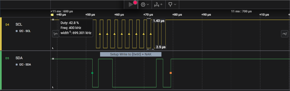
The first diagram shows the expected 400KHz data rate. Look at the call out box on the top left. My mouse, although not shown is across the right side of the SCL pin, where the arrows and times in uS are shown.
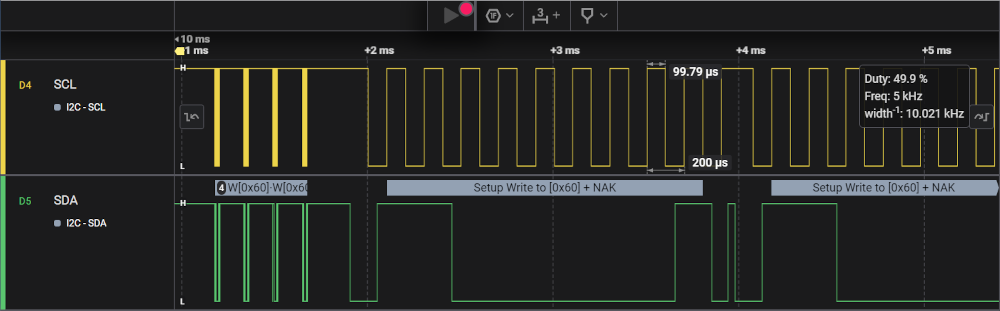
Moving right a little, then zooming out, the above waveform is now one of the the bold yellow bars on the top left. The slow speed can now be seen on the rest of the waveform, again with the call-out on the right and the arrows showing where my mouse cursor is. The frequency can be seen in the call-out boxes in both cases.
This is clearly not the expected behaviour and after a lot of checking, simplification, a bug was logged with Espressif on their git repo, for the Arduino framework (not the native ESP-IDF), since this is what I am using within Platform IO. At this point, the version is v2.0.10. The resulting defect is #8480. Other people were able to confirm the same result. An Espressif engineer going by the great handle of @me-no-dev was working on the problem with a number of other contributors.
During my testing, before logging the bug, I had found that I could work around this problem by forcing two speed changes on the bus. One to an arbitrary value that was different to what I wanted (forcing a change to be written to the device), then resetting it back to the speed I wanted. This is not a fix, but at least the bus was able to work at the required speed. and a workaround function was inserted in front of all I2C commands as a bit of a belt and braces approach until something better and more permanent could be done.
But, what was causing this strange behaviour to occur ? The answer was surprising. I was deliberately trying to talk to some devices that were not on the bus. I2C supports hot plugging of devices onto or off the bus and I have 4 remote modules and 2 expansion sockets on my main board, so I was attempting to detect the presence or not of the remote modules to decide if I needed to get information from remote boards and, in the console to show the presence or not of modules as that can indicate a fault condition if for example a rat chews through the cable that goes to a remote module.
The I2C protocol supports this and indeed the Arduino Wire library that implements I2C has return codes in its endTransmission() method that actually tells you if the remote device didn't respond. The way this is achieved is due to the I2C protocol use of an open collector drivers for all devices on the bus, meaning that any device can pull the bus low, but nobody can pull it high, the pull-up resistors on the bus do that for you. Within the protocol, the slave device acknowledges to the master device that its there by acknowledging, via an ACK signal on the bus by pulling it low at the right point in the protocol. Clearly, if the device is not there, or didn't get the message, then the bus is not pulled low and that is seen by the master as a negative acknowledgement (NACK)
Starting to understand the problem in more detail and because I have a JTAG interface on the board, I was able to fire up hardware debugging mode on Platform IO and JTAG into the ESP32, using GNU Debugger (GDB), to walk through what was happening, along with some reading up on the ESP32 S2 technical reference that explains what all the registers do and how the various peripheral busses (PERIBUS1 and PERIBUS2) work, along with some pointers from Espressif to help narrow down the problems root cause.
In parallel with my testing, a new versions of the Arduino framework was released - v3.0.0 Alpha 2, which related to the ESP-IDF version v5.1.1-577-g6b1f40b9bf-dirty, these require a manual install, since its an alpha release and therefore not visible in the standard framework update tools. Retesting against that code base was required, to confirm if the problem was fixed or not. Testing confirmed that the problem actually got worse, hence a second defect was then raised to allow better tracking, this is defect #8855. We narrowed down the problem to be that as the driver code was assuming that transmission failures meant a bus error had occurred and after several of these, it decided to perform an I2C bus reset, to try and clear the issue, but in doing so, it reverted the clock divider rates to an unexpected value, hence causing the problem.
With the problem now identified, the Espressif's @me-no-dev confirmed on the 13th of November 2023, that the the fix for this defect was in the Arduino framework release v3.0.0. However, by this time, nearly 4 months after the initial bug report, and for other reasons, I had already upgraded from the ESP32-S2 to the ESP32-S3, which didn't suffer from the same problems on the I2C bus as it had different driver code within it, since the I2C feature within the chip has slightly different control register layouts.
Since I had been focused on getting the new hardware built and installed, into the Coop, my free time to check this fix was not available, so I kept it on my backlog and finally picked it up in September 2024. Using the current versions of all components available at that time, they were Arduino IDE 2.3.3, Espressif Arduino code version 3.10RC1 and ESP-IDF release v5.3-466a392a, I was able to confirm that the bug was indeed resolved, which I reported back to the two open defects, allowing them to be closed.
This was a long and interesting path and shows the sort of problems that can come out of the woodwork and impact delivery. The real gains for me personally, was a far greater knowledge about how the different frameworks interact with each other and how the underlying ESP-IDF works, plus some keyboard time in the GNU Debugger (GDB), but using the PlatformIO visuals, and the command line, to interact with the ESP32 at the register level. It had been a long time since I'd need to go to that level in any design and the first time with the ESP32 family of devices. It stresses again the need to read the technical manuals for the various devices, since there is always a lot of info on features and how they work, how the chip is architected, etc.