
The ported code from the version 1 project, along with all the modifications to the development environment, removal of no longer needed functionality, new pin configuration, new chips and revised functionality is now compiling and linking, so it can be uploaded to the board to make it work and allow more exercising of the hardware. Much of the firmware to drive new or improved components is still not there though, there is no GPS module integration as that needs a UART driver to be written, no front panel control, no power module control, just the core, as the aim is Minimal Viable Product (MVP) to allow installation, since code improvements and enhanced functionality will take much longer to achieve.
What this does provide though is network connectivity over WiFi, which enables Over the Air (OTA) firmware updates, a command line interface over the USB UART on the ESP32, this in turn allows for proper diagnostic messages. Both of these make development a lot easier to do.
Development proceeds well and with many of the initial bugs being due to changes to the new hardware and things not being mapped correctly in software due to all the changes, but these were quickly resolved and lots of the previous functionality started to work well again.
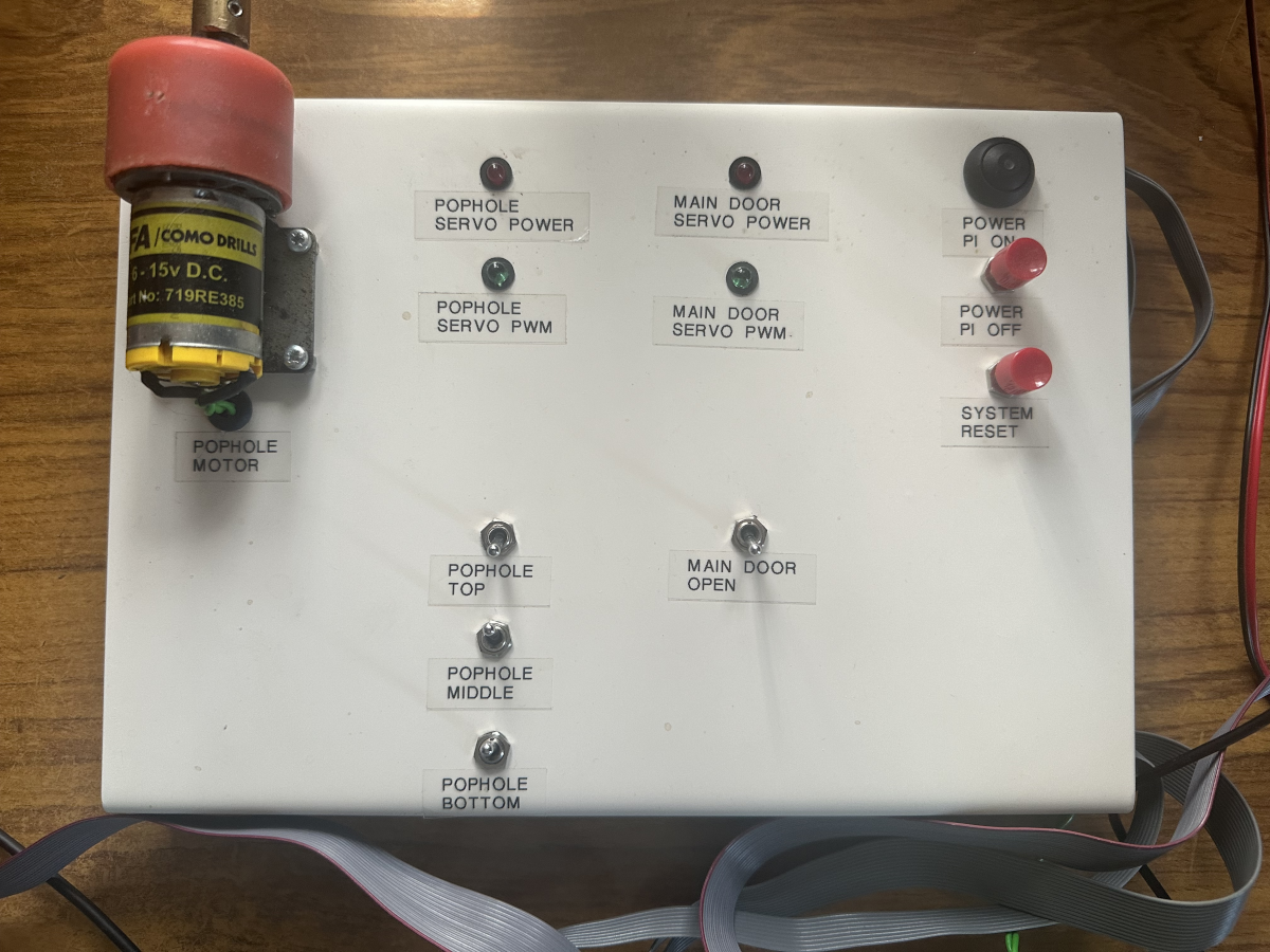
Testing the system requires that input are stimulated to emulate the chicken coop and control outputs can be easily seen, without needing to resort to using the Scope or Logic Analyser. This makes testing a lot simpler to achieve. The solution is to build a test harness, or test fixture. This is simply a folded piece of aluminium with some buttons, switches, LED's and a motor connected to it, it connects to the standard headers on the main unit and shows key signals in an easily visualised manner and provides switched inputs in key areas. The intention being to cause the software to detect changes and act accordingly - at the correct times.
Once that phase of development is working, work could proceed on writing other missing components. The following picture shows the device driver for the dual UART being developed, with some support from the Saleae logic analyser and a USB to UART adapter. There are two ports on each device, one goes to the GPS receiver, the second is to a UART connector, provided for expansion and writing the driver. A second chip provides a serial interface and some control pins to each of the expansion sockets.
The small red board is an FTDI 232R based USB to UART breakout board, connected to the development PC, so that data can be generated and seen on screen and interacted with, using a standard terminal emulator.
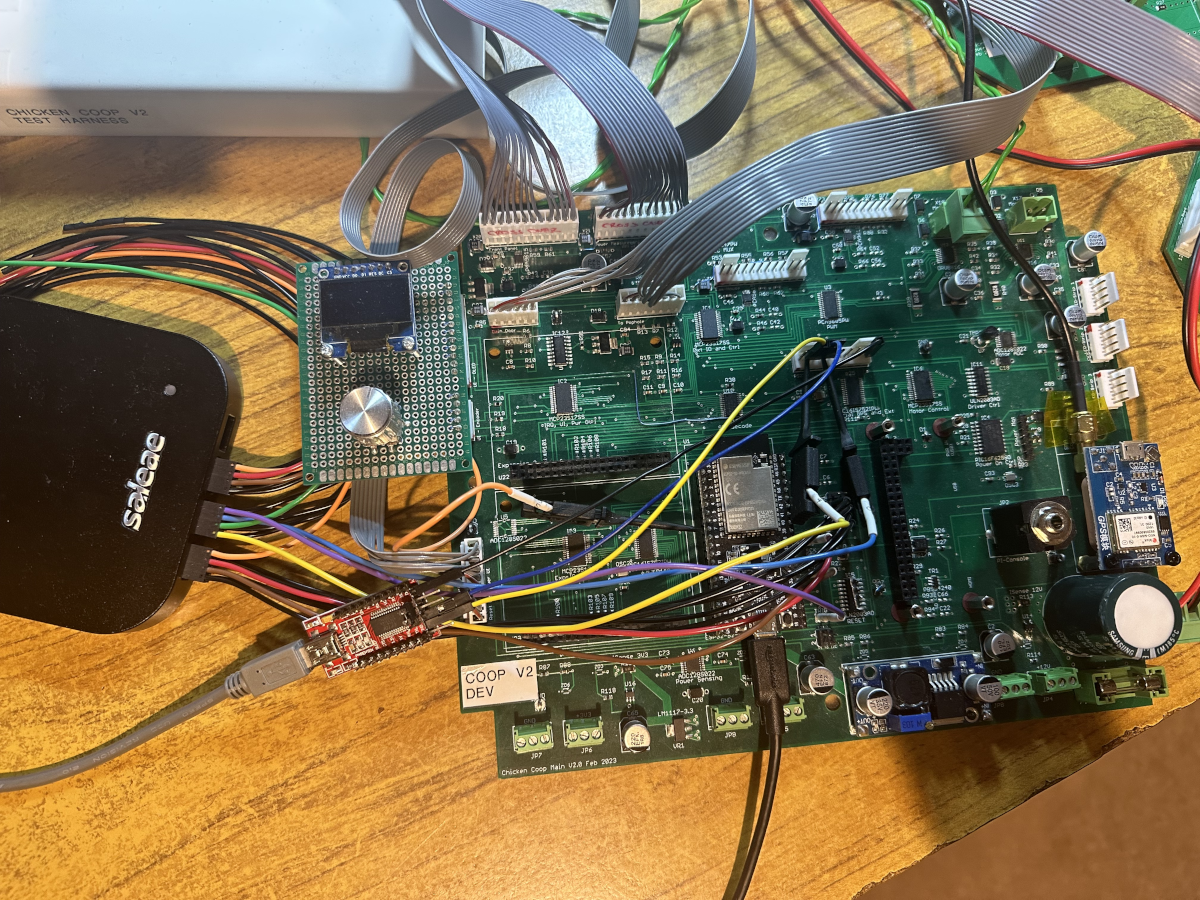
The picture also shows a prototype of the diagnostic display, which has an 0.96 inch OLED display and rotary encoder on it, this allows for much of the local diagnostic interface to operate as it did in the previous v1 design. The difficulty though is that these displays are small and get dimmer over time as the OLED fails and I was down to my last one in the bits box. 1.8 inch TFT displays were dirt cheap, larger, had more colours and could be dimmed, so I added a new upgrade task to the project tracker to modify the board and replace the display with a TFT.
You may also note a couple of additional bodge wires on the PCB (near the middle) and at the top near the external module connectors, the latter being part of two overlapping faults, one of which resulted in the magic smoke being released by the line driver IC's on the remote modules as they had their connector layouts reversed during layout and I failed to notice that during assembly, so power was reversed and that's never a good thing. The second fault was a reversal of the driver pins on the differential line driver and that resulted in the remote I2C links not operating. Again, these were fixed with the tried and tested way and were entered on the project defect tracker and fixed in the updated PCB layouts.