
The electronics and software may be the majority of this project, but when it comes right down to it, those boards need to be installed and protected against the elements and the hard reality of being installed in a Chicken Coop, which involves dirt, cleaning products, through to moisture, bugs and temperature swings through the year. For this reason, a ABS plastic boxes with hermetic seals and brass inserts are used. The plastic will move over the years and the seals will eventually fail, but, if caught in time, they can be replaced. Similarly, replacement boxes are not expensive and they are easy to work with.
The brass inserts, along with some copper grease are added to ensure that the threads do not corrode and being metal, they last a lot longer than screws direct into plastic, particularly when the covers are on and off through the year. All the fixings are Stainless Steel, again to resist corrosion - except galvanic corrosion, which is a different problem, given the brass, copper, stainless steel combination. I know from previous experience that ordinary Bright Zinc Plating (BZP) steel fixings do not last in this situation and the will still rust into brass inserts.
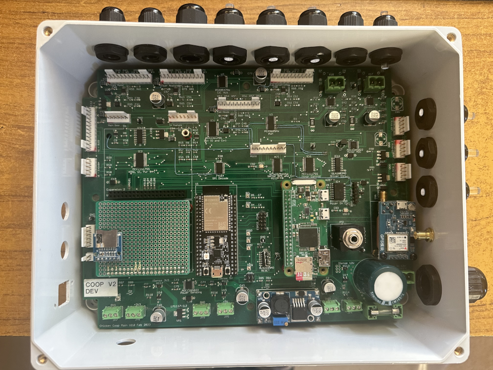
The main box
The main box enclosure protects the main PCB, plastic cable glands are used to allow the cables to enter and seal, keeping moisture and creepie crawlies out. Additional cable entries are installed and clear perspex rods are inserted and tightened down as these are much easier to remove and install, compared to removing the box, or trying to drill a hole in the right place and re-installing everything, its called planning for future change.
The board is not fixed in place in this picture (and its the dev board as that was what wash handy at the time), but it shows how everything will be once its all installed. You may also notice an increasing number of bodge wires as problems are identified and upgrades are performed on the unit. This picture shows the prototype SDcard module in expansion socket 1, this greatly expands the systems command line interface
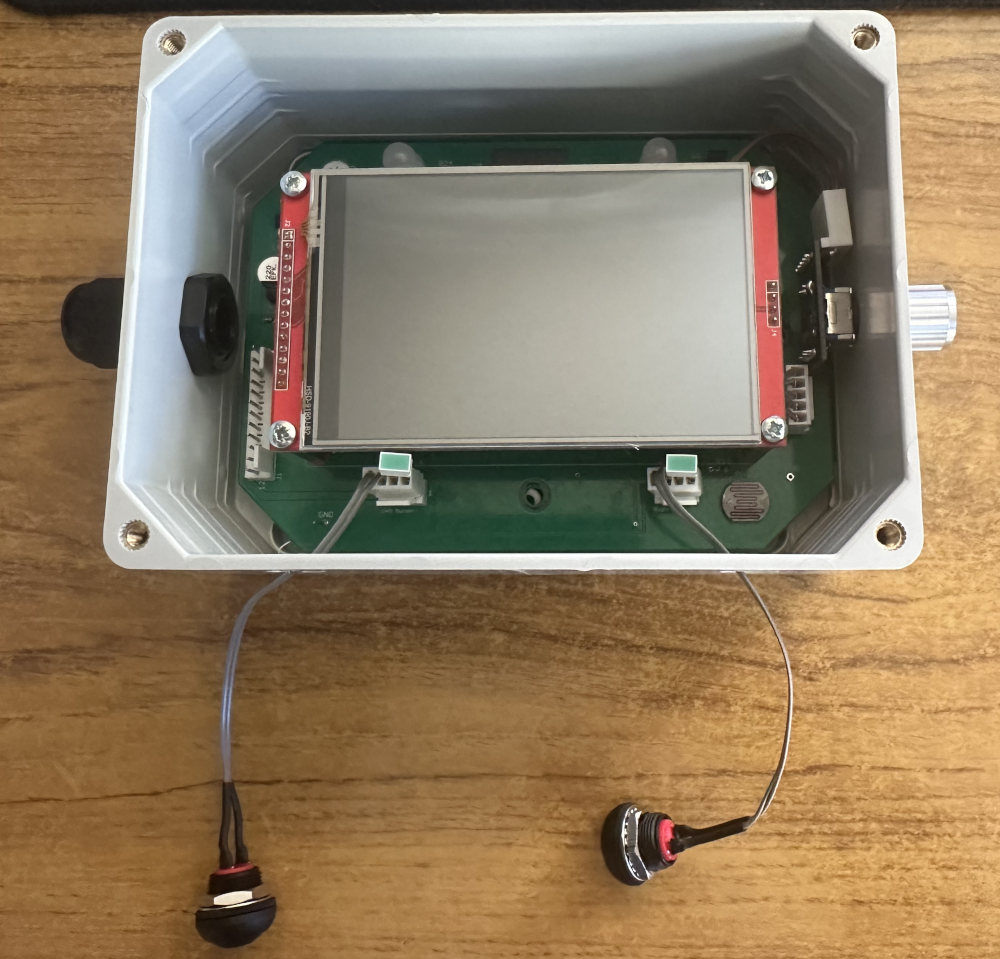
Front Panel
The Front Panel module is fairly basic in its design, however, the position of the TFT display over the ESP32 should be noted. The ESP32's WiFi aerial is deliberately placed above the display since that provides a clearer route towards the house and the access point.
The close proximity between the incoming cable gland and the connector should be noted as this is tighter than I would have hoped for and it makes assembly more difficult than I like. Similarly, the rotary encoder on the right only just has enough space for the connector to be installed. These are all things to try and improve in any subsequent board respin.
The bottom waterproof switches are cabled up and ready to install and the easiest way to place the LED's turned out to be to mount them on the Molex connector. Future versions of the board will have an extra set of pins on the PCB to allow the LED to be placed directly on the board, giving mounting options for both possibilities.
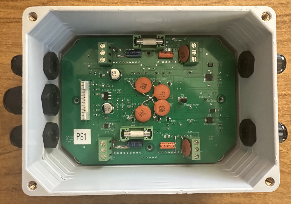
Power Sensing
The power sensing module just needs to take some chunky cables in on its cable runs, due to the relatively high currents they will carry and because some of those cables may be solar panel grade cable. Once in the box, they are terminated on the screw terminals and provide a data link back to the main coop. Cable routing could be better and the connectors would benefit from a slightly larger form factor, since the cables with their butt splice connectors installed are a little tighter than I had hoped for. The next iteration of board will therefore use a slightly larger connector.
A number of additional filtering capacitors and a small bodge wire at the top can be seen in the diagram. These, as with all their predecessors are now resolved in the next PCB iteration. The form factor of the orange 100nF capacitors is not ideal, but it was what I had in my box of spare capacitors and more importantly, they work as required, to remove some noise on sensing voltage dividers, leading to more accurate readings on the ADC's
Protective coatings
None of the boards have any form of protective coatings on them, often called a conformal coating, such a coating can be a specialised chemical coating, or just ordinary spray lacquer in most cases. Its purpose is to provide a barrier between the electronics and any environmental moisture, dirt and other such contaminants and given that lacquer is quite cheap, its a great option to add to boards.
However, my decision is that at this point, it will not be applied to any boards, this is for several reasons, but the largest one is that the system is still in development, so changes will be necessary and ongoing measurements to the board will be necessary over time. Neither of these are easy to achieve with a coating on the boards, since that must be removed first, then replaced.
The approach I'm taking is to leave the boards unprotected and when the rate of change on the boards has reduced significantly, then its probably time to respin the board and get all the updates done, when those boards are assembled, then it would be better to apply a conformal coating.
There is however the problem that not all items can be protected, for example the un-used connectors, TFT displays, SD card readers, fuse holders and a variety of other components and to achieve this, masking is required before the application of the coating, then its removal afterwards.