
Now we have the ability to actually control the Rotator position, we need to be able to turn that into a closed loop system where it can take an angle from the main Arduino and accurately move to that position so that we can point the solar panel at the sun.
As we have a 4 bit encoder on the bottom of the shaft and the zero value of the encoder is aligned with the end-stop jam within the gearbox, which incidentally has the purpose or stopping the wires going up the pole from getting wrapped round and round the assembly and therefore breaking. We can therefore determine within 1/16th of a circle or 360/16 = 22 degrees. This is helpful, but has a number of issues, which are:
- Its not accurate enough to position the panel
- The Rotator can turn a full 360 degrees, so it rolls over at the top of the range, that is the encoder output goes 13, 14, 15, 0 since there are only 4 signalling bits.
- Like any switch, each encoder bit suffers from bounce, so you do not get a clean transition from one segment number to the next. As we have 4 bits, the result is that the number does not change in a linear fashion, 1,2,3,4,5,6,7,8, etc, it will jump around all over the place and the sequence is dependent on where we are in the rotation. The encoder I chose has a binary output, it does not use the Gray code that was developed to try and help minimise the effects of this issue.
- As the encoder is mechanically fixed to to the geared output, the "click" positions on the encoder are not functional, since the large geared output is stronger than the little spring loaded ball bearing that is fitted to 'snap' the encoder to the next position to reduce the switch bounce. The effect is that the unstable period for the encoder is longer than if it just had a knob on the encoder.
- Conversely, we do have a couple of other tricks we can use, that is we know that we are driving a fixed drive signal into the motor and the motor is driving a fixed gearbox, therefore the rotation speed of the output shaft is also fixed, We know by timing it that a full 360 degree rotation of the shaft takes 70 seconds, therefore we can calculate the theoretical position if we record how long the motor has been running for. We can also re-calibrate our known position each time the encoder position changes to a new stable value (i.e. after bounce), this means that we can determine the actual position with accuracy.
The code is therefore written to measure the number of milliseconds that the Rotator has been moving for, this gives us angular measurement to less than one degree, which is far more than we actually need.
There are a couple of gotcha's that we have to work around in the code, they are :
- Depending on which direction we are moving in, the encoder value indicates either the "start" or the "end" of the 22 degree angle of that segment. This just needs to be taken into consideration in the code
- We only know a rough angle when we are first powered up and we can only improve on the actual position when the encoder value changes from one number to another.
- We can detect a stall when we have moved for longer than the time expected to transition from one encoder value to the next and no change has occurred. This either indicates that the encoder is at a limit, or the panel, which is large may be providing resistance against turning. Consider movement on a stormy November day when the wind is blowing against the panel.
- Due to the 4 bit rollover issue, when we measure a zero, but want to move to say segment 2, we may actually be at position 15+1, so if we have not had an encoder change to 1 after the required time, then we need to reverse the motor direction and see if the encoder changes to 15. This allows for us to cater for a reset event that occurs whilst the Rotator is at the upper end of the rotation angle.
Figuring out all of the above takes a fair amount of time. It also becomes apparent that the power transistors will need a bit of help dissipating the heat, so a spare piece of 15mm copper pipe is adapted into four flat copper heat sinks, one for each of the 4 drive transistors. A temperature sensor is also fitted to the unit, so that in the event that we do not move to where we need to, or if we are doing some testing and the units get hotter than normal, then nothing can overheat. This is an issue, since for waterproofing / red mite protection purposes, the unit will be sealed, so disposing of waste heat is a problem as we are in a plastic box which will not conduct heat well. Conversely if we dissipate heat out via say a metal coupling, then we run the risk of igniting something in the coop - in an extreme state. With the help of the temperature sensor, the code now has the ability to detect a thermal overload and stop movement until the temperature has reduced. This shouldn't occur during normal operation as the movement amounts are small during the day, except during the evening (when its typically cooler anyhow), as this is when the Rotator needs to be re-positioned back to the start position for the following day. The logic for this is detailed later. we may however end up fighting the wind during stormy days so this does need to be catered for in the code.
Whilst building and debugging the code, we had some serious problems getting an accurate encoder value - which was assumed to be due to the above encoders mechanical coupling between the shaft and the encoder, but it became apparent that this was not the only issue. Following a bit of investigation with the scope, it was clear that the return signal from the four encoder bits were very noisy and were being misinterpreted due to the electrical noise on those signals.
The reason for this is that I had already taken the design decision to put the Solar Panel Positioner module within the chicken coop, since this would make it a lot easier to maintain than if it were on the pole, as:
- I get the ability to see the LED's on the module
- I can easily connect to it and debug it
- Upgrades are easier
- I don't have to worry as much about the environmental aspects such as water ingress etc
- It's a lot easier to mount in the coop
- I can have a short distance serial interface from the main Arduino to the slave Solar Panel Positioner module and the power cables for the positioner driver are fairly short. The side effect of this is that I have to have a long run of about 15 Meters for the drive and sense signals up to the Rotator and back from it
I reflect on the fact that the standard aerial Rotator uses the same approach of having the control unit off the pole, so its probably OK.
A key difference however is that the standard Rotator uses a transformer from the incoming mains feed and is therefore driven from a pure sine wave, whereas in my design I'm driving it from a modified "sine wave", which is actually a pair of square wave signals that do not have a 50:50 mark space ratio. As those signals have hard edges and I am driving an inductive motor that is more than 15 meters away, there will be some big inductive spikes on the wire that occur at the time the signals change from 1 to 0 or 0 to 1.
The diagram shows the differences between the waveform types. The pure sine wave in red, a pure square wave in green and the modified square wave in blue.
The reason for the problem is that the test harness was built using the final components, one of which was the roll of cable (still in a taped up coil) that would eventually run up to the Rotator. Similarly, a spare, short length of another cable was used for the return run from the Rotator back into the control panel.
What was happening is that the inductive spikes from the coil were, through cross-talk being imposed on the encoder sensing pins. The standard fix for this sort of problem is line conditioning via filtering. Since I've already run out of space in the driver module, I've now got another module to make. I decide that since this is a power and filtering module, wire wrap is not appropriate, so now is a good time to start producing some PCB's, hence the first PCB of the project is born.
The PCB is home-made PCB, rather than a professional one, but nonetheless, some home etching was enjoyed by all, particularly the part of making the Culpric Chloride Etch solution, this was probably due to the colour change and chemicals involved. The PCB was formed in Eagle as a single sided design, printed on drafting paper and transferred to photo sensitive copper clad board before being etched to form the board and then drilled with the Dremel. There is no silk screen or solder resist.
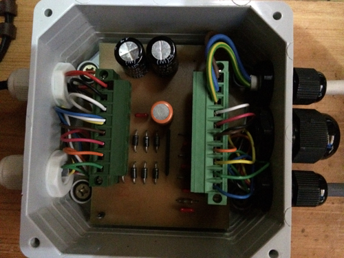
The picture shows the final board. The left connector has the motor driver signals at the top and the encoder signals at the bottom. The right hand connector is identical in layout.
At the top, you can see the non polarised Electrolytic capacitors, since this was a handy place to put them. Bottom left on the PCB are the clamp diodes to remove the large transients beyond the power rails and on the right, under the green connector, you can see the RC filters that remove the fast transients. Encoder positions by definition are very low frequency signals.
Following the implementation of the filtering module, the sensing problems were resolved. This also made it clear again that the project really needs to invest in some professionally produced PCB's. This is currently planned for the winter months and will involve a miniaturisation and attempt to resolve known issues such as SPI programming.