
As there is a lot of external connectivity and all the wires have to terminate somewhere plus we need some space to condition the input signals, we need a main board. I chose to use a standard euro card and wire wrap the board, since I had all the bits and it allows me to easily change the design as we go. The PCB can come later once the defects have been ironed out.
So, the main board was laid out and looks like this.
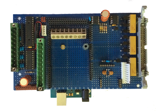
Left to right, excluding all the screw and plug-in connectors, there is a Microchip MCP23017 16 bit I2C IO expander - since you can never have too many IO pins.
Below the expander is a ULN2803 darlington driver array since this takes up less space than discrete transistors. This gives us reasonably powerful open collector outputs which is handy for reset pins and simple control outputs
To the left of the large orange electrolytic capacitor on the top is another Microchip 23FC1025 128KB FLASH chip. This like its peer on the Level shifter board is used to store data through the day that we can graph or process on the Raspberry PI
The top right IC is an Analog TMP36 temperature sensor, this gives an easy way to measure temperature and its used to measure the internal temperature within the control unit -- thinking again about the flammability of the chicken house.
Bottom right, the set of three headers is the footprint for the 16 channel PWM / servo controller, the PCA9865 from hobbytronics
The remainder of the resistor packs and discrete transistors are to control the 7 segment displays via the large 50 pin grey connector.
In the middle, the large open space with the black 0.1 pitch headers is where the motor controller board goes in and connects back through the PCB to the Adruino.
The most frustrating thing about this board was finding out that the Arduino board has an 0.1 inch pitch on all its pins, except for one set of pins that is offset by half of this pitch - presumably to prevent people plugging it in backwards, however this makes getting it through the standard 0.1 pitch euro card completely impossible, that is until the Dremel is brought into play.
The reason this is important is that as we are wire wrapping the board, we have handy pins to drop the Arduino onto. You can just see the bottom USB and power connector of the Arduino from the bottom middle of the picture. When the board is flipped over, it looks like this. The screw and red fibre washer is just there to hold the board onto the main board and stop it creeping off as the temperature changes over time.
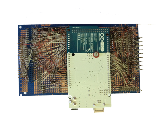
You can see the wire wrapping wires on the back of the board, these look ugly, but they work. Each is a 30SWG tefzel wire and is applied by hand using an automated tool. This technology is really old, but its of interest as it happened by accident back in very early phone exchanges. See the Wikipedia article for more info.
The benefit of wire wrapping is that its easy to prototype with since you can pull off a wire and move it with ease, something you can't do on a manufactured board. The following picture shows the board in close up, notice the vertical pins and the neat wires connected to each. You can get 3 or 4 wraps to a pin, so some planning is necessary to lay things out right.
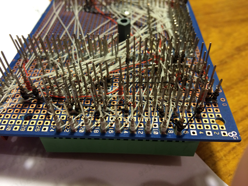
Some pins in the Arduino area have to be trimmed to prevent them shorting against the Arduino board, also some of the pins that are close to the Arduino footprint have to be bent out at 15 degrees or so in order to provide the required space to physically mount the Arduino board onto the adjacent pins. The first fitting was "interesting" as getting all the pins lines up was time consuming, however since then, as everything is now aligned nicely, its easy to get the board on and off as required.