
Little boys are brought up with motors, they are simple, a battery and a motor, possibly even a couple of pieces of wire, this is simple stuff, but that's for DC motors. AC motors are different, there are two coils that share a common pin.
At this point, the project takes an unexpected detour. I've read about how AC motors work and I'm also looking at the 12V DC supply and know that it takes 18V AC to drive the motor, so I start thinking about differential signals to increase the instantaneous voltage on the coils, like you can with speakers and piezo elements, so I start designing a drive board. I also start thinking that one coil is for clockwise and one is for anti-clockwise (please don't ask why)
Ideally motors want a nice clean sine waves to drive them so we need to synthesise these signals. 555 timers were considered that were controlled from the main Arduino, but the logical thing to do is to have a Rotator Controller slave that we just talk to, hence offloading the motor position and movement functions to a microcontroller is attractive, after all a compatible Arduino Pro Mini can be obtained on ebay for about £10 and offers a little more functionality than the venerable 555 timer.
So, we start to play.
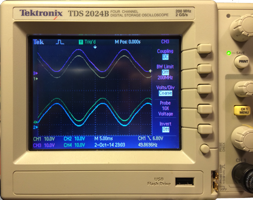
The Arduino generates a couple of opposite phase square wave outputs that are passed through a couple of op-amp low pass filters to extract a pure sine wave from them, we then run that through a couple of bipolar power transistors (TIP121/TIP126), we should be able to strap the motor coil across that and we are done. The scope traces look good, a control input and a power output for each phase that look identical.
A bit of a query comes up about frequency, should this be 50Hz as we are in Europe, or 60Hz like America since it the motor was made there ?. Alternately, does it matter at all, its just a coil, won't the rotational speed just change ?
So, we connect up the motor to test and ... nothing happens, except the transistors get a hot very quickly and the motor hums a bit.
Whats going on, perhaps the drivers are not powerful enough. After a bit of debugging and the loss of a couple of power transistors, its clear that this design is not working as expected. Also I'm concerned about heat - remember the point about chicken coops being a large tinder box and not wanting roast chickens - at least not until we call for one.
After much scratching of heads and reading up on line, we learn about modified square waves driven into power MOSFETS, so that you can avoid all the power loss (to heat) in the linear region of bipolar and MOSFET transistors. The aim of the game is to switch on and off as quickly as possible to avoid power losses and motors are fine with it not being a pure sine wave. The following diagram shows the difference between the waveform types.
So, lets re-design for that then, this sounds a lot better, less power is wasted, less heat generated. A new design comes which looks good on paper and generates the right signals without the motor, but like before, you connect up the motor and nothing happens. This is really strange.
Over the coming weeks, then into months as other things around the house and with the job take priority, much is read and things are re-tested, things are tried; the project is left on the shelf whilst I think of other things. Everything looks OK, and its only a motor, why is this so difficult ?. I add a fairly beefy DC to DC converter to provide the required higher DC voltage so we can drive the signals directly and even consider swapping the motor for a DC one, but can't find the right shaft or fixing method to to drive the existing gearbox with.
The problem starts to become an unresolveable issue that gets bigger over time.
So, I'm going to beat this and we go back to basics, we re-connect the original control unit that shipped with the rotator and take a second look. Whilst staring at the 170uf capacitor, and wondering about the odd value, I recall what I've read about power factor correction and the voltages across the coils needing to be matched. I also recall that Capacitors provide phase shift, exactly 90 degrees worth of it, but its an electrolytic capacitor and we are driving a sine wave which has positive and negative peaks, electrolytic caps can't do negative voltages without going bang. I've been there, done that and am still finding bits of the capacitor 2 years on and remembering the loss of normal hearing for a couple of days.
At this point, I find out that the capacitor, other than being a strange value of 170uF and its an electrolytic, but it also says is NP which quickly gets translated to non-polarised. I didn't know that they even existed. More reading shows that its that capacitor that provides the phase shift, and power factor correction, its not a noise reduction capacitor at all. The capacitor creates the right signal and phase shift on the second coil, the difference between the two coils causes the rotation of the shaft. I've been ignoring the second coil in the design, hence I have not been driving the motor correctly, this is why it doesn't turn.
So I re-wire up the MOSFET driver to provide one phase across the common and a phase of the motor and put the the capacitor on that phase and opposite phase like the original controller does and the motor turns. I had misread the circuit diagram of a simple set of coils and a capacito even though I had read several times how the motors work. In the words of Homer Simpson D'oh.
Right I now understand. I order up some NP electrolytic capacitors from CPC in various values and take a look with different values to see if I can match the amplitude between the two coil signals. If the amplitudes are not equal, then the motor has very low torque, but when they are matched, it's unstoppable. We need torque to turn the panel during windy days when there will be some resistance. The 170uf value gives the same correct amplitude on both coils.
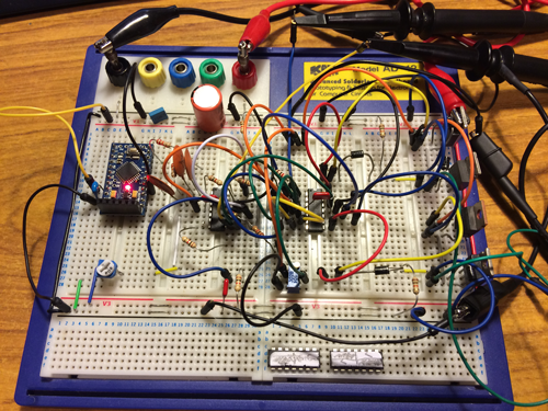
At last we can control a basic motor in either direction by swapping the capacitor and driver pin, so the final design comes up and is tested. Note the two capacitors bottom left and the version 15 or so of the driver board at the top. This has now taken me over 4 month on and off to sort out -- just for a motor. Now we can start to work on actually using the motor to position the panel where we want it.
The resulting driver board is shown above. On the left at the top is the relay that swaps the output signals to the right pins. This is only moved when there is no drive signals, hence removing any arcing on the contacts.
- On the left at the top and bottom are the 4 power transistors that form the two output signals. the top pair are the high side and the bottom pair are the low side.
- In the middle is the op-amp that produces the required gate voltages to rapidly turn on and off the transistors.
- To the right of the op-amp is the Arduino Mini Pro. Above this is are two indicator LED's that show if the Rotator is running left or right.
- The green connector is the connection to the main module, it provides power, serial communication and a reset pin.
- At the bottom left is the LM2577S DC-DC buck/boost converter, this takes the 12V supply voltage and boosts it to the required level to get 18V levels across the motor.
- On the bottom right is a LM2596 based switched mode regulator that drops the 12V supply voltage to the 5V levels required to run the Arduino.