
The Rotator has arrived from America and duly gets powered up, tested and taken to pieces, its effectively a small 18VAC motor, a set of gears and a sturdy metal box.
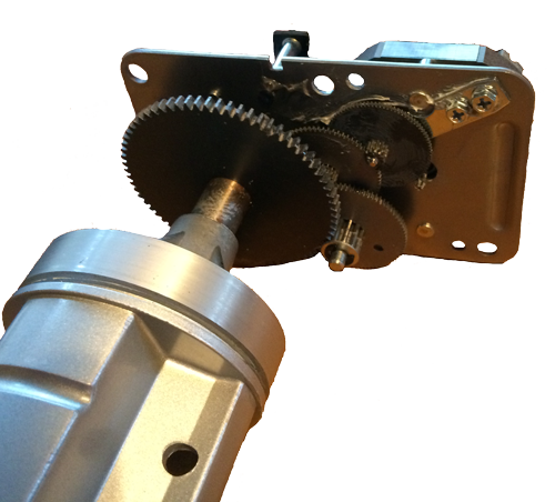
The rotation is limited by a metal rod that is welded to the final gear and a couple of pins that stick up from the gear below. Basically the motor runs until it jams on one of these mechanical limit switches. There is no electronics here, its purely mechanical. The motor just cant rotate once it jams. The main control unit (after getting into it) is a similar approach with a dial driven from a similar motor (ahh, a spare for the future ..), so it looks like Dad was right (again) .. 1960's technology in 2014 !.
Whats nice about the unit is that even when it jams, the current to the motor is only 1.7 Amps. I'm a bit worried about the tiny little drive shaft from the motor, its bottom right of the top right gear, it looks too small and fragile, but time will tell. There are 3 pins from the motor to the original control box, which are wired as a common and two phases on the AC motor. There's a 170uf electrolytic capacitor in the box too, I assume that's some form of noise suppression or something ?
The secondary bearing that goes up the pole to reduce the stress on the bottom bearing is nothing fancy, its just a bearing, but at least I've got all the bits now and we can start making things.
Having never used AC motors in designs before, I've had a bit of a read up on Them. There are two coils in the motor, each is driven with a 90 degree phase shift relative to the other and depending on if the phase shift if +90 degrees or -90 degrees, then that decides which way the motor runs, that should be a doddle to do with a bit of electronics.
However, the first problem is how to sense where the shaft is actually pointing, so a Graywell 4 bit encoder is purchased. We just need to strap that onto the end of the shaft at the bottom of the main gear. The problem is that the shaft only sticks out far enough to catch a fairly meaty circlip.
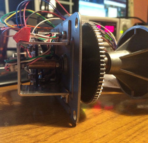
Cue Peter and his metalworking skills again. After a "planning session" that involved a fair amount of wine and some IT fixes. We schedule the next day for a bit of time in the shed. Soon after, we have a thread in the bottom of the shaft with a lock nut that doubles as a height and rotator angle adjuster. We also have a brass bush and a fixing plate for the shaft encoder, so I can now sense the motor position to 22 degrees by dividing 360 degrees by the 16 segments on the encoder.